I must say that RDCF550 schematics are quite accurate, someone said on another forum that he would try to do an X-Ray on the board, which would complete the schematics but he didn't. Lets see If I can find out something today!
Nothing conclusive yet. I removed U5 and U6 and added L1... and still short between 5V and GND...I am desperately searching for the 5V path to see if I can isolate the issue and will start removing all the capacitors but this does not look cool...U5 was difficult to remove even with soldering tweezers and chipquik. I even screwed up one pad but I am used to repair that... The problem now is that U5 and U6 will probably cost me 5$ each... so I might start thinking about a new board...
I must say that RDCF550 schematics are quite accurate, someone said on another forum that he would try to do an X-Ray on the board, which would complete the schematics but he didn't. Lets see If I can find out something today!
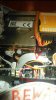
RDCF5500 did scan the PCB. See below. If you visit his picture storage you will find high resolution picture.
(The size picture below have been reduced for viewing here)
Yeah, and I only found out because I was desperate and started removing everything...
The picture is not a scan, it is only the first layer disvovered with either acid or sanding. I have some discovered traces after removing the paint from top and bottom, but not yet sure if there is a fifth layer. In three weeks I will come back with results from the re assemble....
It's still a capacitor whether a surface mount, electrolytic or the size of a nickle it's still a weak component and due to failure at some point in time.
Last 2 posts forgot the CONTEXT of this thread: CRASH. crash means PHYSICAL damage, not leakage, drying out, etc. Physical damage. Even ceramic SMD caps can have a corner smashed and make the metal layers touch each other at the edge around the mica.....
hi sir can you give me link for that inductor. i also fried this inductor. also what current status for this problem. one more what tempetature hot air you set during this process.
hopefully you can help me. thank you
hi sir can you give me link for that inductor. i also fried this inductor. also what current status for this problem. one more what tempetature hot air you set during this process.
hopefully you can help me. thank you
If you an electronic parts store in your area you could buy just 1 or 2 replacements they are rectangular surface mount 1uh inductor. Or you can buy 20 of them online from China and wait almost a month to receive them. Type is into the ebay search box surface mount 1uh inductor. I have no idea what HOT AIR settings you'd need to mount it to the board haven't done that kind of work in 20 years.
If you an electronic parts store in your area you could buy just 1 or 2 replacements they are rectangular surface mount 1uh inductor. Or you can buy 20 of them online from China and wait almost a month to receive them. Type is into the ebay search box surface mount 1uh inductor. I have no idea what HOT AIR settings you'd need to mount it to the board haven't done that kind of work in 20 years.
This site uses cookies to help personalise content, tailor your experience and to keep you logged in if you register.
By continuing to use this site, you are consenting to our use of cookies.