NOTE: None of these are official schematics, they are only as accurate as I can make them and subject to change without notice
So far I've done the..
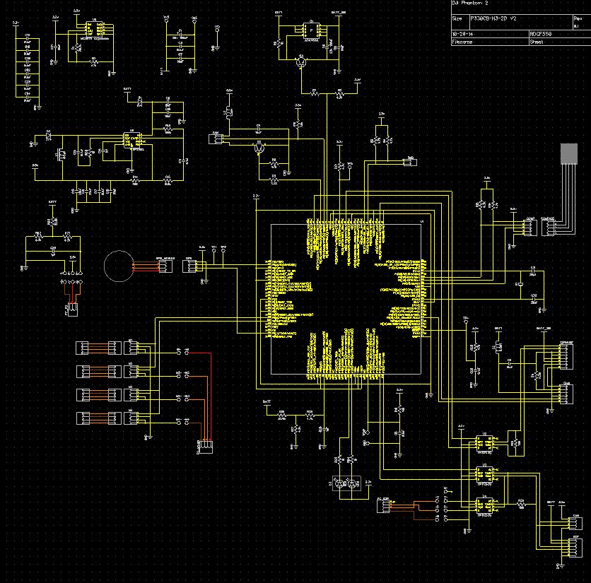
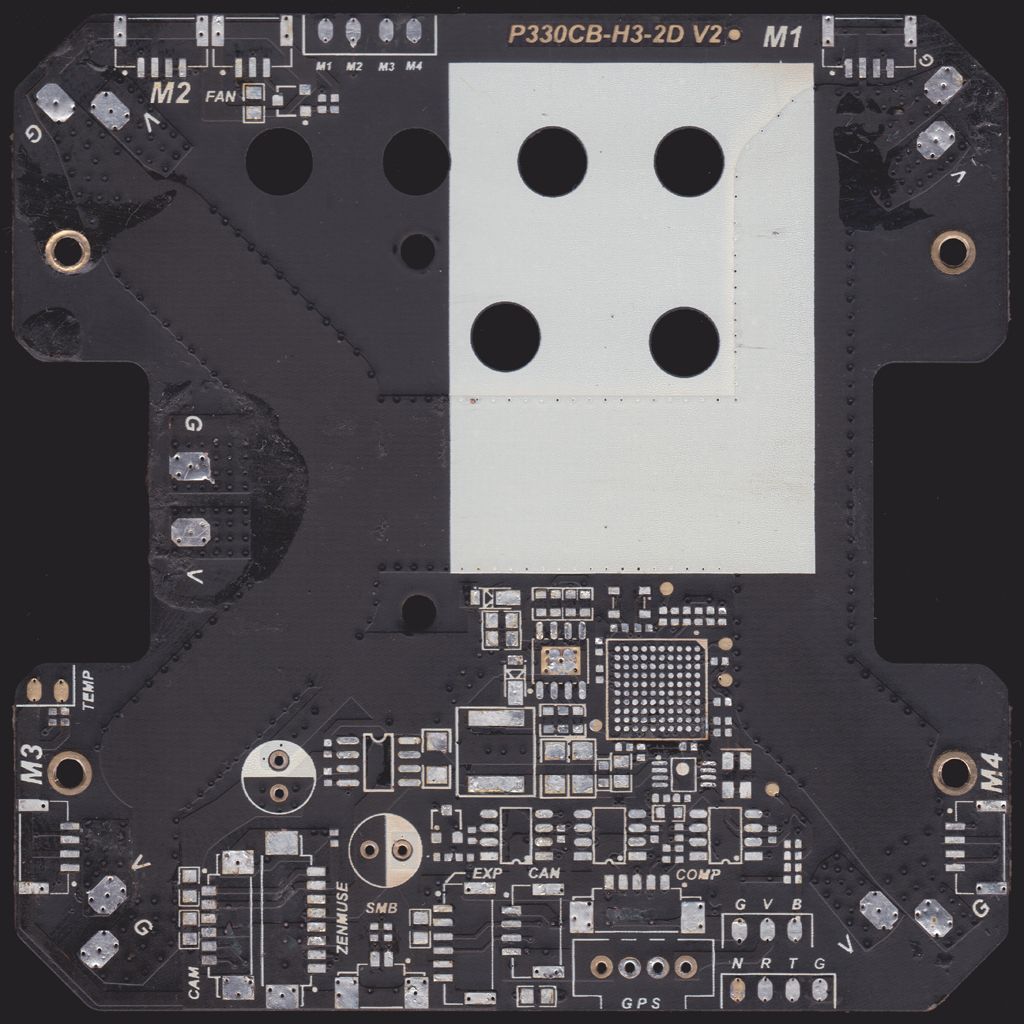
P330CB-H3-2D V2, Central Board
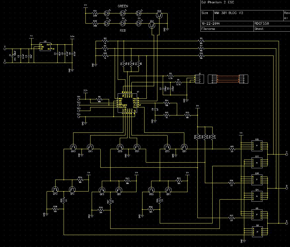
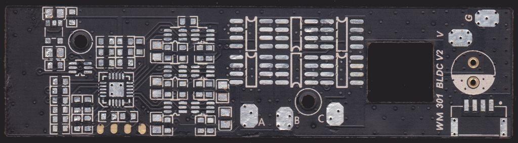
WM 301 BLDC V2, ESC (NOTE: The V2.0 ESC is the same Hardware, but has different Firmware on it for the new Motors)
These are the LoRes versions, attached are the HiRes schematics I've made up.
Central Board
 ESC
ESC
Scans of the boards I've done so far.
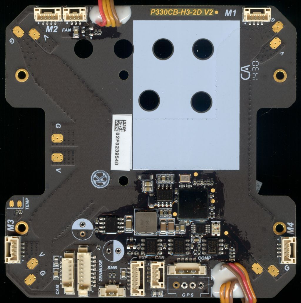
CENTRAL BOARD Note: There are no components on the bottom side, so no bottom scan.
 CENTRAL BOARD NO COMPONENTS
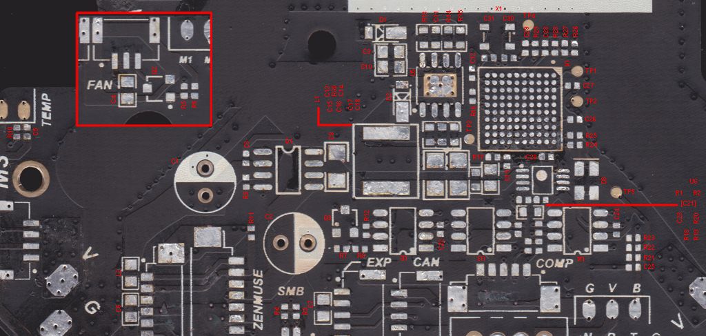
 CENTRAL BOARD DESIGNATORS
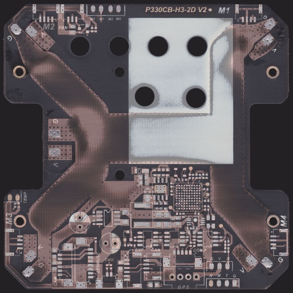
 CENTRAL BOARD STRIPPED
 50% overlay
 CONNECTORS
SMB 2 pin, COMP 5 pin, CAM 6 pin, ZENMUSE 8 pin - Molex PicoBlade 51021
ESC 4 pin, CAN 4 pin, EXP 6 pin - JST GHR-xxV-S Series
CAN Connectors (Accessories) - Molex Micro-Fit 3.0 43640 - 43645
________________________________________________________________________________________________
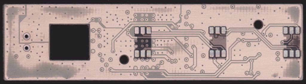
ESC NO COMPONENTS TOP
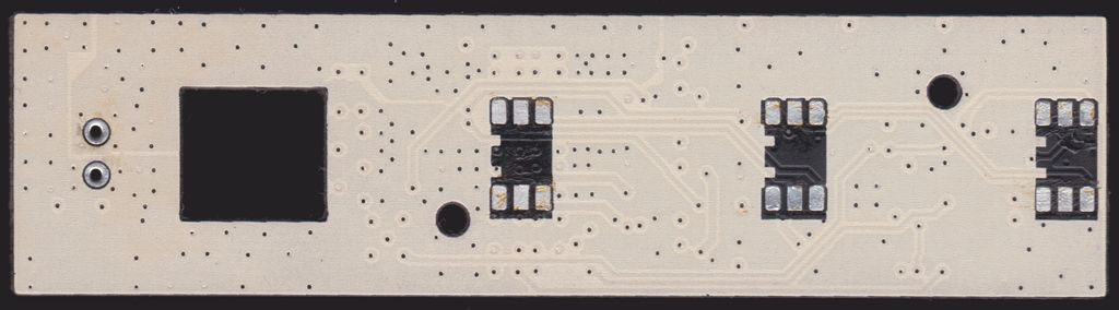
 ESC NO COMPONENTS BOTTOM
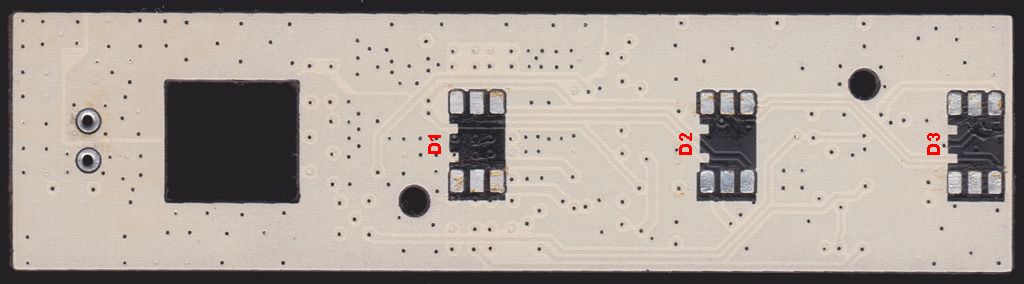
 ESC DESIGNATORS TOP
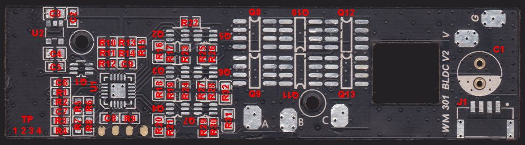 ESC DESIGNATORS TOP
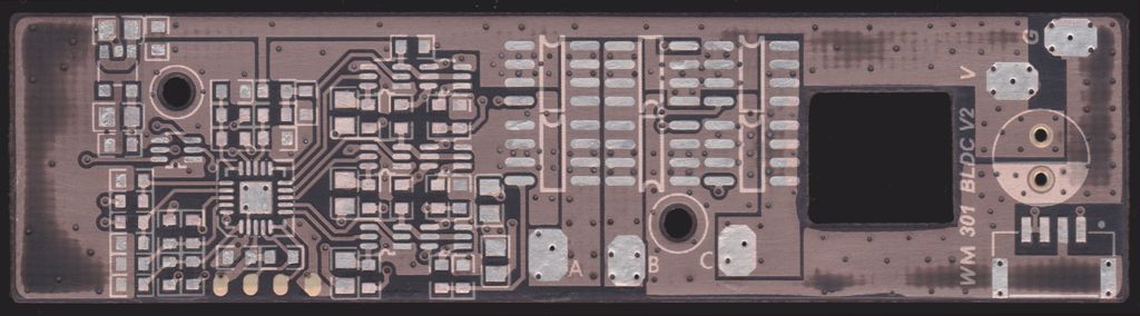
 ESC TOP STRIPPED
 50% overlay
 ESC BOTTOM STRIPPED
 50% overlay
There are 6 connections to the ESC board from the main board in the P2. Two of them are for power.
V = Battery Voltage
G = Ground
Then a 4 pin connector.
1 - Orange = 1kHz
2 - Brown = Ground
3 - Orange = Motor control from Flight Controller, 400Hz
4 - Orange = Motor control from Flight Controller, 400Hz
Note pins 3 and 4 are connected together on both the ESC and main boards, so a 3 pin connector could have been used there, so not sure why that was done exactly.
The Motor is controlled by the Duty Cycle of the 400Hz signal, the same for how any Digital Servo uses that information for it's position. These are roughly the measured Duty Cycles for Off, On and Full speed.
37% Duty = Motor Off
47% Duty = Motor On (spooled up, idle)
71% Duty = Motor at full speed
The more interesting thing here is the 1kHz wire. It's Duty Cycle is what controls the LEDs on the ESC board.
10% = Off
20% = Red
30% = Green
40% = Yellow/Orange (Red + Green)
50% = Off
60% = LEDs go along with motor signal, i.e. the front LEDs flashing with start up sound (Motor on = LED on, Motor off = LED off)
70% = Off
80% = Off
90% = Off
100% = Off
So combining those Duty Cycles in various orders and time frames will give you the different LED flashing that goes on.
ESC beeps. (NOTE: The Motor makes the sounds you hear, so no motor or badly damaged one connected to the ESC means no sounds)
Eight beeps from a Low to Hi in a row (1.2.3.4.5.6.7.8...) followed by four single beeps (8..8..8..8) Means a normal start up (NOTE: On the V2.0 ESC the four single beeps do not happen, only the (1.2.3.4.5.6.7.8...) are heard for that version of ESC.
One quick repeating beep (8...8....8....) Means there is no 400Hz signal from the FC
Two quick repeating beeps (8 8..8 8..8 8..) Means the Voltage on the V pad is 5.9v or less.