Here are step by step instructions:
1. By during this mod you assume all risk of Any damage to the phantom 2 and to any damage done to anything the phantom hits if it crashes .DO THIS MOD AT YOUR OWN RISK
2. Discharge the battery fully by running the motors till the stop, at this point turn the battery off and then on and run the motors again . Keep repeating this till the battery refuses to turn on again
3. Google "freeing the phantom 2/ vision from 0roprietary smart battery's" on this thread it will show you in great detail how to take the battery apart. This is the thread I used to take mine apart.
4. Once you have the battery taken apart simple grasp a cell and pull it straight back, the terminals will simply pull out of the battery, I had to rock a couple of cells back and forth but the terminals freed them selfs .
5. Once all the cells are removed cut off the terminals from the board as they are no longer needed
6. Solder a black wire and red wire to your male deans connector ( or what ever type of connector your batteries have). You can get the wire and connectors at any hobby shop.
7 . Solder the red wire to the "power +" on the lower PCB board
8. Solder the black wire to the "bat -" on the lower board with the other black wire. You can also just de solder the original black wire from the boards and just solder the new black wire to the upper board
9. Now locate the small ribbon cable that goes from the upper board to the lower board. It will be black in color.
http://static.rcgroups.net/forums/attac ... G_5237.jpg
10. Looking at the connector from left to right ( black side on left red side on right) the first to wires are the communication wires that tell the phantom that the battery is a dji battery and also supplies the voltage readings for the cells , so don't touch these. The next four wires are the cell wires you need to cut them right at the connector on the lower board( the one with the power connector on it )
11. Follow these wires to the connector on the lower board and cut them right at the connector leaving the first two wires connected to this plug
12. Take a cell balancer lead extension and cut off the female plug
13. What I did was just splice the black DJI wires that went to the lower connector onto the the balance leads in the following order
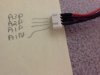
Red wire of the balance lead goes to the A3P wire or the one closest to the red dot on the upper board
The next wire of the balance lead goes to the A2P wire
The next wire of the balance lead goes to the A1P wire
The last wire of the balance lead goes to the A1N wire
You can see the above names for the wires on the PCB and all I did was meter them out and label them with a piece of tape
14. Once the splices are done insulate each of the with heat shrink or tape
15. Make a hole in the case as far forward as possible and feed the connectors thought it
16. Notch the cap for the wires and the reassembly the case and wires, you don't have to cut the case to bake it shorter but I did just to make it smaller