Said could be, and it's obviously bad as it doesn't get that hot during normal operation or typically fail even after being knocked around quite a bit.
If the FW is ~3.0 or higher, then removing the GPS will not let the motors spool up, so it will not work in ATTI mode as it will not start up.
EDIT:
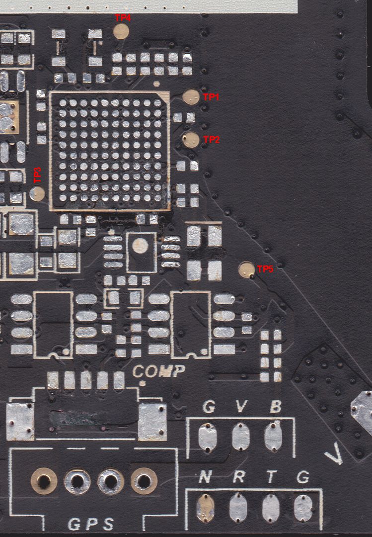
GPS Connector checks on Central board.
NOTE: Make sure there is NO battery in the Phantom 2 for these checks, you're testing for Resistance here and want no power going to the board.
Unplug the GPS module from the Central board.
Set the DMM to measure Resistance (Ohms).
Place the Red test lead on TP5 of the Central board. Place the Black test lead on TP1. The reading should be 1.8M or right around there, 1.5M to 2M is fine.
Place the Red test lead on TP5 of the Central board. Place the Black test lead on TP2. The reading should be 1.8M or right around there, 1.5M to 2M is fine.
If either of these readings are different, especially if they are a much lower value, then suspect the Central board to be bad and it will need replacing.
These should be double checked at the GPS connector on the Central board also. The 2 center pins are the same as the TP1 and TP2 spots.
Place the Red test lead on TP5 again, then check the Resistance on each of the center pins with the Black lead, they should be the same as what was measured on the TP1 and TP2 spots. If they are different, then there is a problem between the connector and the MCU on the Central board.
Voltage checks.
NOTE: Take care not to short out anything with the test leads while poking around in there, as there will be power to the circuits for these tests.
Unplug the GPS module from the Central board.
Set the DMM to measure DC Volts.
Put the battery in the Phantom 2 and power it up.
Place the Black test lead on TP5 of the Central board. Place the Red Test lead on TP1. It should measure around 2.3v or so.
Place the Black test lead on TP5 of the Central board. Place the Red Test lead on TP2. It should measure 3.3v.
Place the Black test lead on TP5. Place the Red test lead on pin 1 of the GPS connector. Pin 1 is the one that it closest to the CAN connector and is the one that the Red wire form the GPS module plugs into. It should read 5.5v.
Turn the Phantom 2 battery off.
Really about all you can do for checking the GPS module, without getting extensively into it, is to do some Resistance checks on the GPS module connector.
Unplug the GPS module from the Central board. At the connector on the GPS module, there are spots where you can probe the connectors for the wires.
Set the DMM to measure Resistance (Ohms).
Place the Red test lead on the spot for the red wire. Place the Black test lead on the spot for the Brown wire. You'll get an erratic reading at first, then it will settle down and sit around 200k or so and slowly drop in value. This is normal.
If you get a fixed Resistance value that is lower right off the bat and see no changing at all, then there is an issue with the GPS module.
Place the Black test lead on the spot for the Brown wire. Place the Red test lead on one of the Orange wires. It should measure around 3.6M or so. Then move the Red test lead over to the other Orange wire, it also should measure around 3.6M or so.
If either of those measurements are much lower, then the GPS modules is bad.