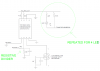
I STARTED A REVERSE ENGINEERING OF THE CONTROLLER PCB.
DOES SOMEONE WANT TO HELP ME?
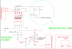
EDIT1: I added some corrections in red color, to my first schematic.
EDIT2: CW2015CSAD5U2 is a a fuel gauging system for lithium batteries. It reads voltage and it give output on a serial line. You will find datasheet online.
THESE ARE THE VOLTAGE MEASUREMENTS WITH THE BATTERY PLUGGED IN:
-THE BATTERY VOLTAGE WITH THE CONNECTOR PLUGGED IN THE PCB IS 8,27VOLT
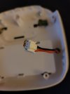
-ON THE PIN 2 OF THE CW2015CSAD5U2 I MEASURED 3,45VOLT INSTEAD OF 4,13!!! THIS COULD BE STRANGE, in fact voltage raises a little bit when the problem was solved. This point on the board corresponds to the TP_VCELL pad, located on the right of the battery connector (shown on next image).
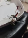
EDIT3: I welded a wire on TP_VCELL pad and I applied 4volt (negative on the ground of the board) with external power supply, then I plugged the full charged battery to the controller, then I switched on the controller and problem was solved (full battery charge is shown). This is due to the fact that the CW2015CSAD5U2 estimates the battery charge status as soon as you plug in the battery. Of course by removing the external 4 volts, the battery status estimation slowly returns to its original value.
NOTE: acoustic buzzer is active if flat cables are disconnected, but this is not relevant.
EDIT4: I tried to unweld CW2015CSAD5U2 but i was not successful. May be the component is glued. I could try to remove the glue with a scalpel. I ordered one online.
Some measures/tests:
-ON THE VCC_MCU_3,3V I MEASURED 3,3VOLT ONLY WHEN THE CONTROLLER IS ON.
-On DRAIN pin and SOURCE pin of mosfet NXP PMV65XP I measured 3Volts both when controller is ON and OFF.
-On GATE I always measure 0volt. This means that the circuit correctly powers the CW2015CSAD5U2.
EDIT5: I connected clock and gate to a oscilloscope and i tried THE AUTOMATIC DECODING OF I2C DATA. The ARM requests register 04 (State of Charge of the battery) and CW2015CSAD5U2 returns 01 (1%), then the ARM requests register 02 and 03 (analog battery voltage) and CW2015CSAD5U2 returns 2B31 (LSB is 305uv, then 2B31 is around 3,37 volt (voltage on pin 2 of the CW2015CSAD5U2 was around this value).
EDIT6: So at the end I suspect there is a dispersion from TP_VCELL pad to ground. By measuring resistance between TP_VCELL and ground and between TP_VCELL and battery positive pin, i get the same value in ohms. I could try to replace the capacitor, otherwise it could be a problem between PCB layers.