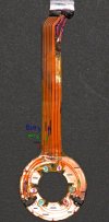
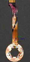
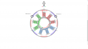
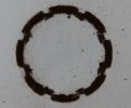
Yaw motor device. The motor burned out, tried to rewind and recognized the design. This motor works harder than others - it holds everything else. Below is a photo from a magnetic bell, magnetic dust on paper has created an imprint. There is nothing special - 8 poles, very symmetrical. This is how it should be in a brushless motor. But there is a very narrow gap between the poles, and that's where the sensors are located. The direction of the drone forward / backward in the picture is vertical. Next, I checked the operation of the sensors. These sensors are analog Hall sensors. Power can be seen from the diagram in the photo. When the signal increases on one, the signal increases on the other. I don’t know how the drone’s logic works, but if you use the voltage difference from the sensors (I used a multimeter), then in the range of 0-30 degrees the signal is positive to the left, negative to the right. When the camera is rotated +/- 45 degrees, the signal difference disappears and there may be problems. Perhaps this is related to the discussion above. The location of the sensors is very critical, as can be seen from the diagram. If they are placed closer to each other and the yaw angle is reduced, the sensor signal will be proportional to the angle, there will be no signal break. Another option is to glue neodymium magnets with a large gap between them. Motor data: Wire 0.1 mm, 40 turns per tooth, winding order AaABbBCcC, wind large letter clockwise, small letter against. The motor makes 72 steps per revolution. In my case, the crash hit the insulator on the yaw motor board, as you can see from the photo, the winding connections and the "-" bus occupy a significant area of the board, and the insulator is paper-thin. It is better to connect the wires on the motor stator.