Thes steps are described in the first post. Before using ftp you should be able to connect to the terminal. After you boot from backup copy and mount original file system to /mnt/flash you'll be able to use either linux terminal and vi editor or ftp to edit currupted files. Don't forget you should only change files inside /mnt/flash and don't touch backup file system.hi there, please reply, after connecting usb ttl to remote board, how to mount to ftp file system? need help


You are using an out of date browser. It may not display this or other websites correctly.
You should upgrade or use an alternative browser.
You should upgrade or use an alternative browser.
Yes, someone asked it here already and was told that sin and sout is what you're looking forHi
Which ports should i connect on phantom 3 4k controller?? There is no dedicated tx rx ports on the board.
Is it sout and sin ??
Can I parallel SIN/SOUT with UART's RX/TX Pins.
Thanks for Help
Thes steps are described in the first post. Before using ftp you should be able to connect to the terminal. After you boot from backup copy and mount original file system to /mnt/flash you'll be able to use either linux terminal and vi editor or ftp to edit currupted files. Don't forget you should only change files inside /mnt/flash and don't touch backup file system.
Did use putty or filezilla on windows or Linux? Where the is back backup copy held to?
It good if you give details instruction, so I don't mis anything out or corrupt the whole system.
I'm using mac. Backup copy of flash is located the same place as the original one. You're just able to switch to it when U-Boot bootloader is active in terminal. Then backup is loaded and it looks and behave completely like original flash. It created wifi and you access it via FTP if you like. But first you need to mount original corrupted filesystem to arbitrary folder inside backup filesystem, say /tmp/flash. After it you can fix corrupted rcS inside /tmp/flash/etc/init.d/rcS using vi or ftp again. Please tell me what is unclear in the first post and I'll make adjustments, cause it seems to me quite clear, but I'm a programmer and use linux quite oftenDid use putty or filezilla on windows or Linux? Where the is back backup copy held to?
It good if you give details instruction, so I don't mis anything out or corrupt the whole system.
")
I'm using mac. Backup copy of flash is located the same place as the original one. You're just able to switch to it when U-Boot bootloader is active in terminal. Then backup is loaded and it looks and behave completely like original flash. It created wifi and you access it via FTP if you like. But first you need to mount original corrupted filesystem to arbitrary folder inside backup filesystem, say /tmp/flash. After it you can fix corrupted rcS inside /tmp/flash/etc/init.d/rcS using vi or ftp again. Please tell me what is unclear in the first post and I'll make adjustments, cause it seems to me quite clear, but I'm a programmer and use linux quite often
Press ESC to abort autoboot in 1 seconds
ar7240> setenv bootargs board=DJI-WM305 console=ttyS0,115200 root=/dev/mtdblock5 init=/sbin/init mtdparts=ath-nor0:256k@0k(u-boot),64k@256k(u-boot-env),896k@320k(kernel1),3008k@1216k(rootfs1),896k@4224k(kernel2),3008k@5120k(rootfs2),64k@8128k(art),3904k@320k(firmware1),3904k@4224k(firmware2),8192k@0k(all)
And then
ar7240> bootm 0x9f420000
This will allow you to boot backup copy of system. After that you'll be able to mount main root filesystem:
mkdir /tmp/flash
And then mount it:
mount -t jffs2 mtd3 /tmp/flash
Then you can go to /tmp/flash/etc/init.d and repair the rcS.
**********************************************
I'll probably use unbuntu,as mostly use Windows and abit of Ubuntu
I had look at your steps, did you used Gedit for example to view and edit init.d file
For Example:
gedit /tmp/flash/etc/init.d
what needs to be changed in the init.d file?
As haven't had look what contains in the init.d file.
Did you just save the file and did you use any unmounts commands?
cheers
I'm using mac. Backup copy of flash is located the same place as the original one. You're just able to switch to it when U-Boot bootloader is active in terminal. Then backup is loaded and it looks and behave completely like original flash. It created wifi and you access it via FTP if you like. But first you need to mount original corrupted filesystem to arbitrary folder inside backup filesystem, say /tmp/flash. After it you can fix corrupted rcS inside /tmp/flash/etc/init.d/rcS using vi or ftp again. Please tell me what is unclear in the first post and I'll make adjustments, cause it seems to me quite clear, but I'm a programmer and use linux quite often
Most of it staring make sense, Until UART turn and connect to remote and see what going...
init.d is a folder, though I agree that it's name is confusing, it contains rcS file which should be fixedwhat needs to be changed in the init.d file?

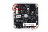
Well done!! fantastic work!Guys, finally, the win! I've recovered both remote and drone. I found proper TX RX GND pins on gimbal board. It's definitely harder to disassemble but it was worth it. Here are the pictures of pins you need to connect with your UART adapter.
View attachment 57657 View attachment 57658 View attachment 57659
Other steps are completely the same as for remote controller, this steps you can read in the first post. Thanks everyone for this achievement!
- Joined
- Jun 18, 2016
- Messages
- 13
- Reaction score
- 0
- Age
- 27
Hi
Can anyone detail a step by step guide to unbricking the RC. I am not a programmer or competent in this field. So please help those of us that don't understand this.
I understand that you need a usb to serial connector and basically solder it to the WiFi board, but from that step everything is blurry. How do we connect now?, which drivers do we use?, which terminal software do we use?, this backup where is it or do we download it, if so where do we place it.
Thank you.
Well, I received some news from my local drone shop which sent the case directly to dji... Here's what dji replied about signal disruptions:
“Hello,
this is not a firmware issue.
During the update one of the parts was damaged and will have to be exchanged here.
If you absolutly want to try a downgrade do this:
Start the complete system and connect to you device. Open the app.
In the white mainscreen, tap and hold the Academy button for at least 5 Seconds. The screen will turn black.
Then you can select and download a firmware (be sure to be connected to the internet) and install.
You can test it afterwards, but I do not believe it will solve the issue.
Best Regards,
Technical Support
DJI GmbH”
Well, I received some news from my local drone shop which sent the case directly to dji... Here's what dji replied about signal disruptions:
“Hello,
this is not a firmware issue.
During the update one of the parts was damaged and will have to be exchanged here.
If you absolutly want to try a downgrade do this:
Start the complete system and connect to you device. Open the app.
In the white mainscreen, tap and hold the Academy button for at least 5 Seconds. The screen will turn black.
Then you can select and download a firmware (be sure to be connected to the internet) and install.
You can test it afterwards, but I do not believe it will solve the issue.
Best Regards,
Technical Support
DJI GmbH”
I believe this won't work, as I can' connect the rc to p3s? I tried similar attempt putting a earlier firmware version on sd card and powering up the p3s, it's goes through motions of updating, and amber lights just keep on flashing.
Has any one successfully recovered their P3s and rc yet?
Last edited:
- Joined
- Mar 8, 2016
- Messages
- 48
- Reaction score
- 12
- Age
- 27
i recovered my rc but can not recover drone wifi module. has someone wifi module from air unit as a spare? i will buy it
i recovered my rc but can not recover drone wifi module. has someone wifi module from air unit as a spare? i will buy it
How did you recover your rc? I have you tried beshanoe suggestions using UART connected and mounting a image.?
I didn't explain myself correctly, the issue I was encountering was about a 5.8 gHz disruptions that were leading to the bird's return to home. I didn't brick the remote since I used notepad++ without changing any permission. The hack worked for both drone and remote but my issue was still here, that's why I sent my stuff back to the local drone shop.
- Joined
- Mar 8, 2016
- Messages
- 48
- Reaction score
- 12
- Age
- 27
the solder point u2_rx torred off. it is not more on platine. I do not know how. Can I use instead U2 solder points the U1 solder points on upper left corner? When I use the u1 solder points PUTTY can read something but the characters are weird/strange, so i can not read. Look at the picture, that shows the terminal. It is an example. But the same appears to me when I connect to U1 solder points.
Attachments
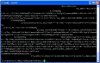
I believe it has connect u2 see beshanoe postthe solder point u2_rx torred off. it is not more on platine. I do not know how. Can I use instead U2 solder points the U1 solder points on upper left corner? When I use the u1 solder points PUTTY can read something but the characters are weird/strange, so i can not read. Look at the picture, that shows the terminal. It is an example. But the same appears to me when I connect to U1 solder points.
Similar threads
- Replies
- 13
- Views
- 5K
- Replies
- 6
- Views
- 11K
- Replies
- 245
- Views
- 52K
- Replies
- 2K
- Views
- 382K