How to add a remote channel & power port to Phantom 3 & 4

Joined
Jan 5, 2016
Messages
543
Reaction score
109
Age
53
Location
New Orleans Louisiana area
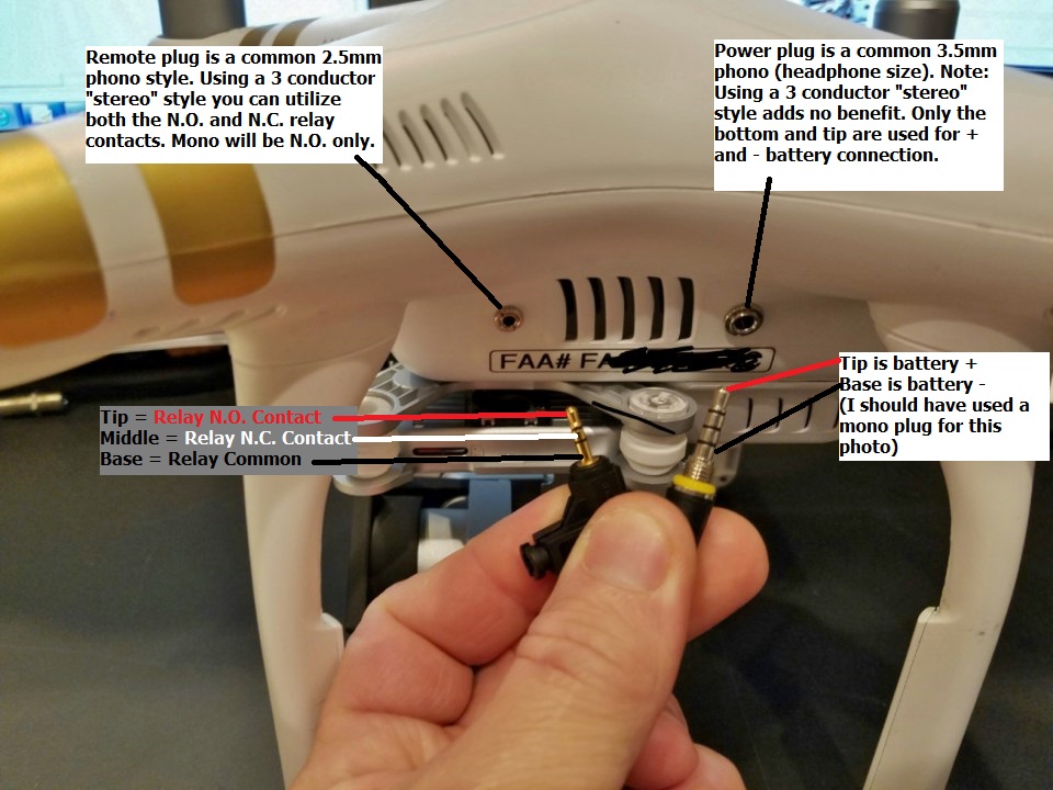
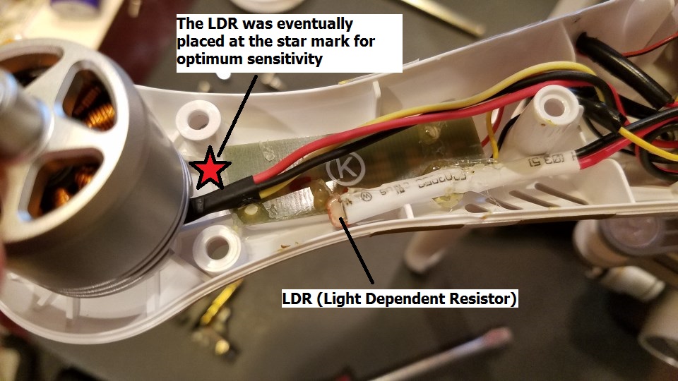
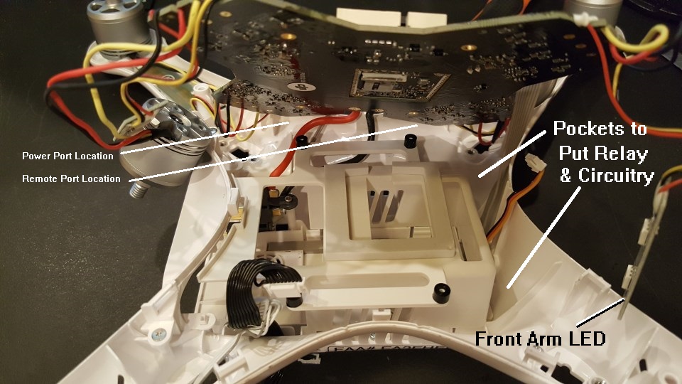
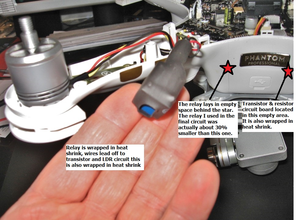
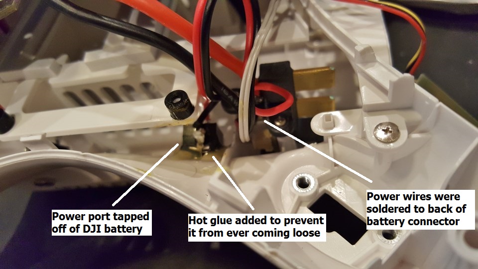
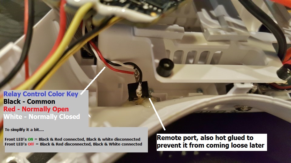
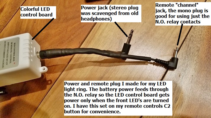
I wanted a way to remotely turn on some lights that I made for my P3P. Unfortunately the Phantom has no extra channel capability so I needed to add a relay that can be triggered from the front LED's. Easy right? just hook up a relay coil to the front LED wires... wrong! The front LED power is not enough to power a relay so I have to make something based on what I saw someone else made to trigger a drop mechanism. The basic premise is that a LDR (light dependent resistor) drops its resistance when the front arm LED shines on it. That allows power to flow and "turn on" a transistor, that in turn finally powers the relay's coil. I made this so that it can all fit inside the P3 and I installed phono jacks to allow me to plug into the relay contacts and power tap off of the DJI battery. For the remote jack I used a 2.5mm phono jack and for the power plug it is a standard headphone size 3.5mm phono jack. I liked how the jacks could be mounted by just drilling 2 small homes and they are held in place with a metal ring nut. I also went ahead and added a bit of hot glue so they won't come loose anytime soon. I liked the phono jacks because they are so common that donor plugs are everywhere around my house. I won't be using much amperage from the DJI battery for the safety of my bird so I didn't really need a high amperage jack like you would use for an extra battery pack. This is just for low power items so you don't have to add extra weight of another battery. Even a little 9v square cell is kind of heavy. Overall I am pleased with how it came out. I tested it yesterday and it was too sensitive during the day. The ambient daylight shining up into the LED arm lens was enough to turn it on, even without the red LED on. The solution for this is to partially mask the LDR to make it less sensitive, or adjust the size of the bias resistor in the circuit, etc. I use this to trigger my lights at night so it works fine for my purposes for now. I labeled things in the photos so it should be pretty self explanatory. The relay jack has 3 wires so you can do "normally open" or normally closed based on the LED light being on or off. The power jack only has 2 wires so a stereo plug won't hurt anything but you only need the base and tip like a mono plug. I am posting this in case someone else wants to do something similar. Let me know of any improvements you make if you build one for your Phantom.

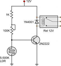
This is the basic circuit schematic

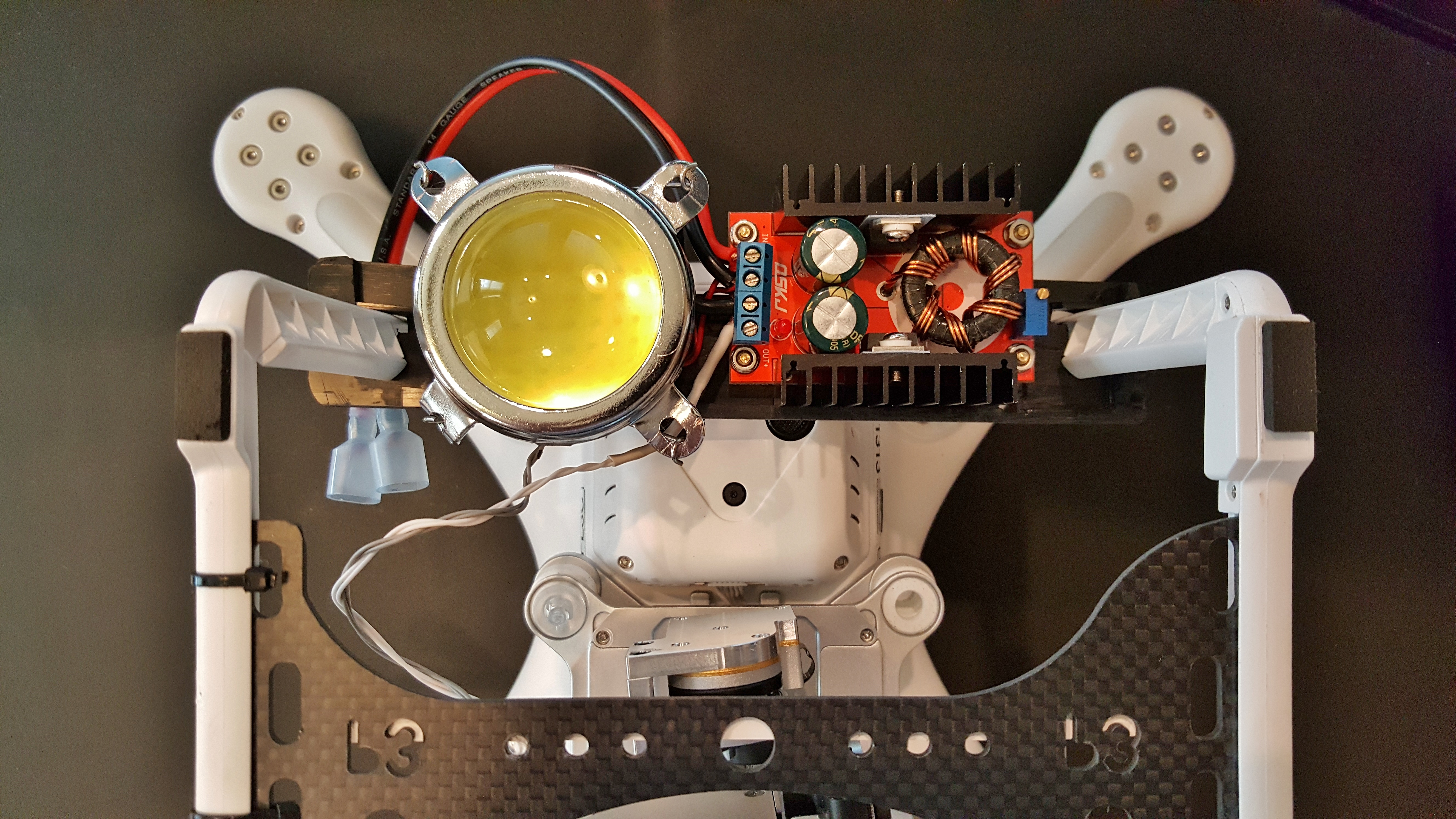
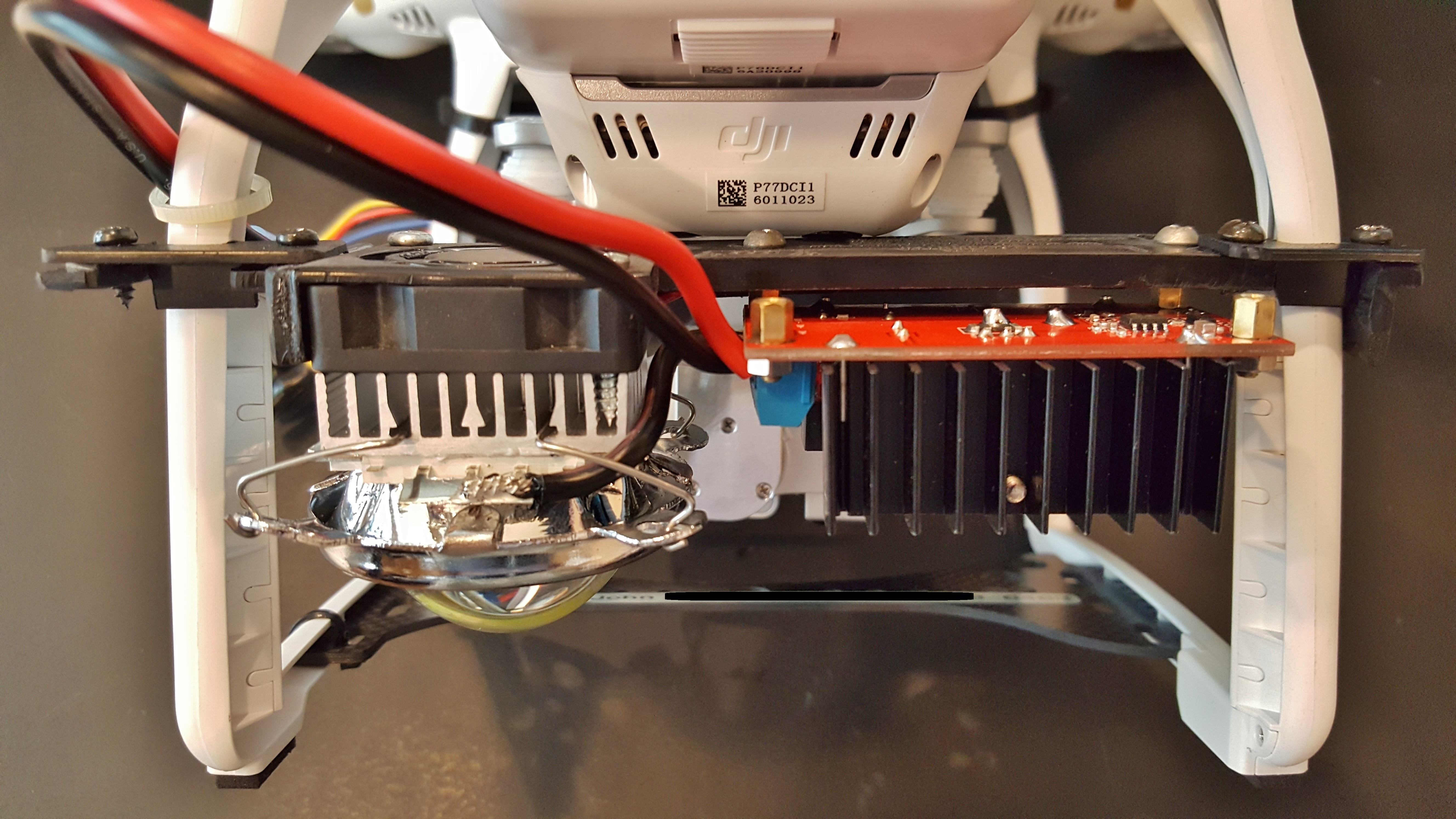
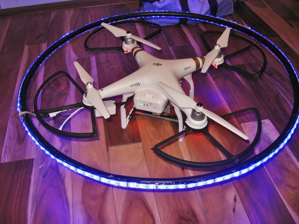
This was my first time using it last night. It works great!

Here is a short video of the light ring in action. I taped over the other stock LED lights so my drone was invisible until I turned on the UFO lights.
 
Last edited:
I finally updated the thread with the circuit schematic.
 
That's so far and above my Phantom 3 Pro' call of duty, it borders on being somewhere between MJ's "Bad" & "SICK"

Thanks for posting and sharing your clever design and mod.
Actually it's just another cool looking UFO, for the books... Ha

RedHotPoker
 
  • Like
Reactions: JonEQuest
Thanks, LOL. It took longer to do the remote channel mod than the light ring.
 
  • Like
Reactions: Energy Guy
Hi Jon, have you try to put a opto-triac or even a solid state relay? maybe will be better solution than the LDR
 
This is beautifully executed, simple best and functional. I wouldn't be braveenough to use a 3.5 mm TRS for the power connector though. While you can't short between tip and ring/sleeve while inserting the mechanical design I wouldn't trust in this application, was never intended for this application.
 
Use a BC547 - they have much more gain [ usually at least 3x more - i.e. 600 as against 200] than the 2n2222, and because of that, are much less temperature sensitive and have a much better "knee" in their turn-on characteristics. Especially useful with LDRs I had thought about doing exactly this to mine - trouble is, work keeps getting in the way. I wouldn't suggest the phono jacks & sockets - they are a fire waiting somewhere to happen when you have high current-capable batteries connected directly to them.
 
you could use a low power source (.7vdc) to just switch on a transistor. as in a small current or voltage at the base allows a larger voltage to flow through the other two leads (from the collector to the emitter
 
Or try using aFET - they can switch the load directly if you make the +ve of the lights joined to the battery + supply, & the fet pulls the -ve of the lights low. They turn on at around 5v on the gate, so your ldr circuit will work if you put the ldr in the top leg & the adjustable resistor in the bottom. Your schematic would make the relay be normally pulled in, and releasing when it sees the light.
 
Built one up quickly. LDR is under tape covering front lights. Works fine.
 

Attachments

  • nightlite for p3.pdf
    15 KB · Views: 923
Here it is. A bit quick & dirty, but I wanted it to shine straight down without getting into the camera. I put 4 x 1N4007 diodes in series with the + line to the led strip to drop the voltage to near 12v - it gets a bit hot with 15v. Draws about 200ma@12v. I took the wiring straight down, rather than down a leg, as that will probably interfere with the compass, and/or the 2.4ghz system. The actual circuit is inside a heatshrink package & that is stuck onto the case with double sided tape. With care, the tap off the battery connector can be done without opening the case.
20170113_121123.jpg
20170113_121141.jpg
 
Last edited:
Hi Jon, have you try to put a opto-triac or even a solid state relay? maybe will be better solution than the LDR
No need for a triac.This was done months ago and works flawlessly. I only use the power out for low amperage devices. The light ring does not draw a whole lot of amps. As far as using a phono jack for power, it has been done before. I have some 5.8ghz video transmitters that actually have a mono phono jack end for the wall transformer to plug power into the devices. The light ring kicks *** and because it is made onto prop guards and the power for it plugs in, it works like an accessory that I can snap on and plug in with no tools, then remove again in 30 seconds. This is the power/remote plug I made. Power is routed through the remote relay so I can turn it on and off from miles away using the C2 button.
P.S. I painted my drone that is why it looks darker.

110.jpg
 
Last edited:
Here it is. A bit quick & dirty, but I wanted it to shine straight down without getting into the camera. I put 4 x 1N4007 diodes in series with the + line to the led strip to drop the voltage to near 12v - it gets a bit hot with 15v. Draws about 200ma@12v. I took the wiring straight down, rather than down a leg, as that will probably interfere with the compass, and/or the 2.4ghz system. The actual circuit is inside a heatshrink package & that is stuck onto the case with double sided tape. With care, the tap off the battery connector can be done without opening the case.View attachment 73252 View attachment 73253
I did the heat shrink thing myself. It keeps things from sparkin'. I also love to light up things under the bird. This is a 100watt LED it draws several amps so I need to use another battery.

I am replacing the mercury switch with a relay that works off my remote channel.
 
Last edited:
You can use exactly the same circuit as I used on an external battery. It was only the led strip getting warm, not the fet. That is good for 25A. I assume that you have a mercury switch on the camera gimbal at present, since you can't program C1, 2 to turn the arm lights on & off?
 
I used to use the camera gimbal with my mercury switch and didn't like it much. That is what made me want to make my LDR/Relay control that I started this thread to share. Now I can turn things on and off with the remote accessory plug. That is the small phono jack. I wired the relay/jack where it can trigger for normally open or normally closed depending on what you need. You decide which poles to use by the 3 contacts of the phono jack. I just have not gotten around to making the phono plug cable for my LED spot light yet. The cable shown is the one I made to power and switch on and off my UFO light ring. The dark drone makes it easy to make my Phantom appear out of nowhere when I turn the lights on. I simply tape over the green lights if I want it total stealth at night.

Speaking of heat, the prop wash does an incredible job of cooling down anything. My 100watt LED would make a large aluminum Pentium heat sink too hot to touch within a few minutes on the workbench. Now on the drone it never gets too hot, even with the wimpy video card heat sink I have on it thanks to the wind from the props. All I did for cooling was drill a bunch of holes in my plastic bracket. Most of the parts except the buck converter and LED are old PC parts I scavenged from my junk pile. The plastic bracket is the back of an old IDE removable hard drive tray.
 
No need for a triac.This was done months ago and works flawlessly. I only use the power out for low amperage devices. The light ring does not draw a whole lot of amps. As far as using a phono jack for power, it has been done before. I have some 5.8ghz video transmitters that actually have a mono phono jack end for the wall transformer to plug power into the devices. The light ring kicks *** and because it is made onto prop guards and the power for it plugs in, it works like an accessory that I can snap on and plug in with no tools, then remove again in 30 seconds. This is the power/remote plug I made. Power is routed through the remote relay so I can turn it on and off from miles away using the C2 button.
P.S. I painted my drone that is why it looks darker.

View attachment 73255
If it was a quality phono jack (also known as RCA) as opposed to a headphone connector I would be more comfortable. The wall wart feeding your 5.8ghz senders is incapable of delivering a fraction of the current available from the LIPO pack if things go south. I have had these connectors fail in service more than once handling milliamperes at 2V peak. Seems to be a mechanical issue shorting tip to sleeve which is a result of insertion/removal. I wouldn't trust it as a potential dead short failure mode across the power source that supplies the AC. No issue in the AV sender use scenario, worst that can happen is the protection will trigger in the supply and you miss some TV.
 
I agree about the power but I don't use it for any significant amperage. For my big LED light it has it's own battery. I may swap out the phono connector. I planned the remote trigger to be the small RCA and the reason the power is the 3.5mm RCA is simply because it was what I had on hand at the time. The power jack was actually an total afterthought I did at the last minute. My main project was making the accessory trigger. Then I figured why not have a little power jack in case I need it for something small. I have thought of using a barrel connector too but I really don't use the power one much.
 

Recent Posts

Members online

No members online now.

Forum statistics

Threads
143,094
Messages
1,467,600
Members
104,980
Latest member
ozmtl