You have options on powering the vTX.
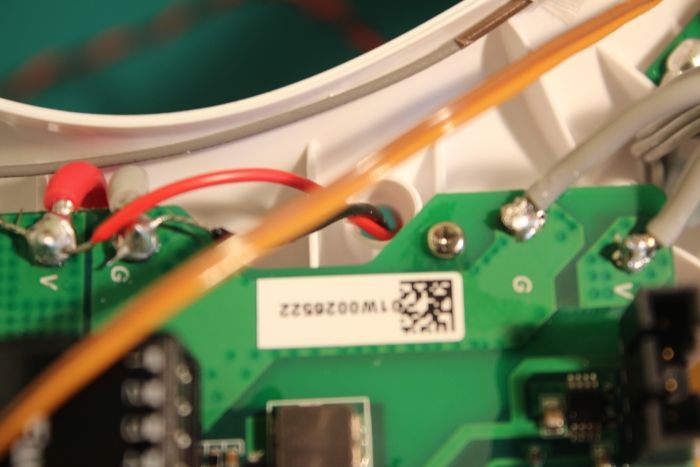
To break it down into actual wires you should have a Red, Yellow & Brown coming from the plug of the upgrade board (that plugs in behind the 8 pin Zenmuse cable on the board (it is the one missing in your current pic!). This is:
Red: 5v VCC
Yellow: Video Output from Zenmuse
Brown: Ground
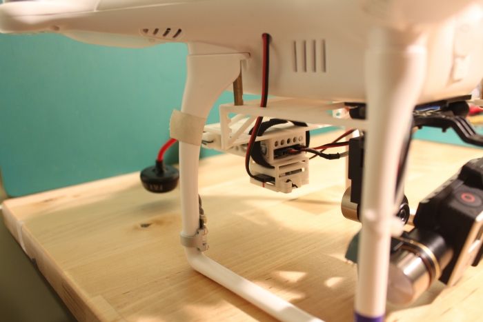
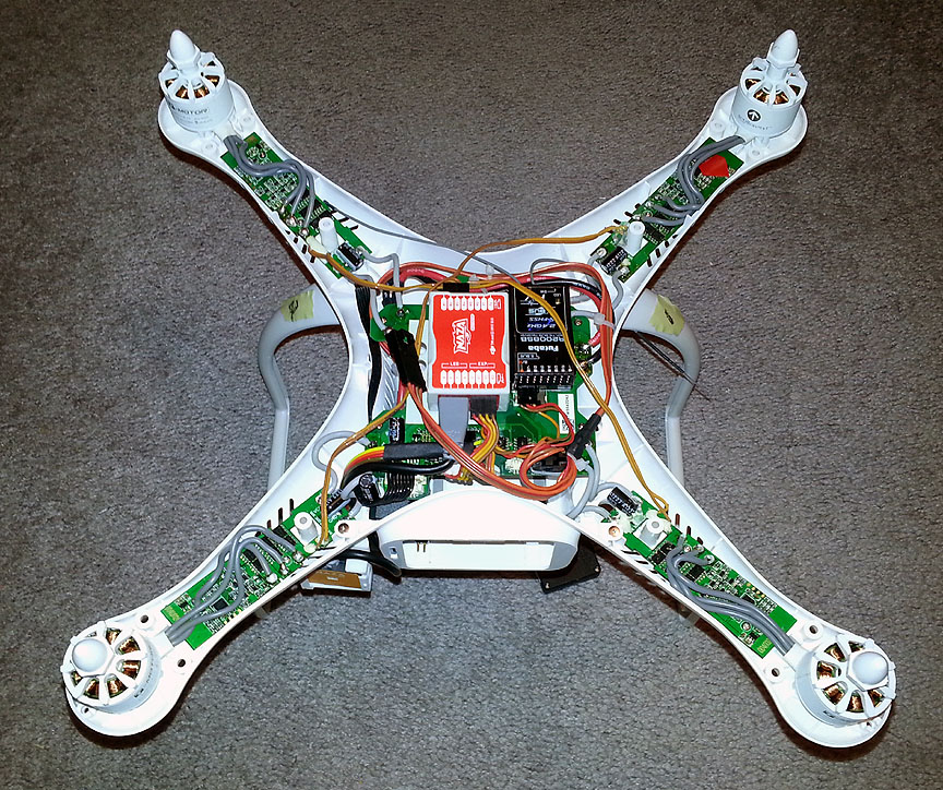
If you use the power filter then you need to get a 12v supply to it first.... I have the filter and personally I soldered a 12v Aux power (like the old days) and poked it out of the handy hole in the P2 shell (below):
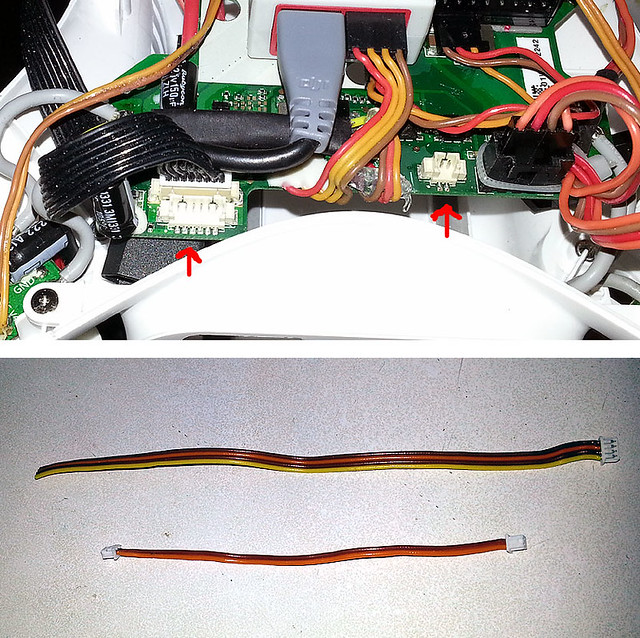
Next I stuck a 4 pin servo plug on it (only using the 2 outer pins). That goes to the filter balance port (see below):
Of course you then use the supplied cable between the filter and the vTX for power.
If you choose to power the vTX
with the power filter then as far as iOSD goes you will only use the
Yellow and
Brown coming from the upgrade board. These will need to be wired into the INPUT of the iOSD (and the output will go to the vTX).... The red wire being obsolete, can be taped off (or heat shrink the end) cause you won't need it and won't want it shorting stuff out!
If you choose not to use the power filter then you can power you vTX from the Red wire. That makes it sound a little neater but think it out in your head first... you will end up running all 3 wires out of the shell, the red will need to get to the vTX (which it won't cause it is always too short!) and the yellow and brown wires still need to go into the iOSD input. That is why I ended up using the filter.
Personally I found that at short range there was little difference using the power filter but at 500m+ range the signal from the vTX to the goggles was better with the power filter in the loop (less lines). This wasn't exactly a scientific test, more an observation and it may have had nothing to do with the filter!


") )
)