final post on the subject....I learned a lot from the discovery.
Here are the results of my testing using heatsinks and thermal grease or tape. Not scientific by any means, but good enough for me to choose a solution that will help dissipate heat off the wifi module’s chips. My typical flying ambient will be about 95⁰F. My hope is to improve the unit’s ability to keep cool, which is supposed to reduce my loss of FPV or outright failure of the wifi module.
Again, take the information for what is being offered, derive your own opinion and plot a resolve based on your abilities or needs. I’m just sharing data with the community. Besides, RTF is just the box you opened on day one, it’s the box of worms you’re dealing with today if you’re reading this.
Thermocouple data loggers were EL-USB-TC set at 1 sec record interval. All the tests were done over three days, I have a life beyond this hobby. High Temperatures after 15 min, ambient 72⁰F for test 1 & 2, original thermal grease. “Covered”, was a simply paper towel to stop direct flowing air and not in contact with the module.
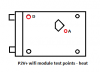
1. Heatsink was a modified copper sink designed for video card chips, pre-applied 3M 8810 thermal tape. Its dimension were originally 14x14x12mm, which had to be re-sized to fit into the diamond indention on the cover - basically 10x10mm. So I lost about 50% of its footprint. Further I had already known that this heatsink would be too tall for the phantom cover to be installed. Heatsink height was left unmodified for tests.
Uncovered
A 128⁰F w/HS - A 134⁰F w/o HS = -6
D 136⁰F w/HS - D 144⁰F w/o HS = -8
Covered
A 144⁰F w/ HS - A 150⁰F w/o HS = -6
D 152⁰F w/ HS - D 157⁰F w/o HS = -5
Air flow with or without a heatsink is a big factor, I saw a 16⁰F difference on average. I typically saw temperatures stabilize at about 12-13 minutes into the tests, never ran the tests longer to confirm otherwise. Further I felt typical run time with P2V batteries was on average 18min, so again time of tests were good enough for my needs.
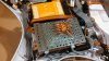
2. Testing with the wifi cover off, with existing thermal grease still in place and uncovered to allow airflow. Point A, the actual chip surface, reached a high temp of 135⁰F. Whereas point D, the RF shield, reached 128⁰F. Point D was my surprise based on the application of thermal grease. Thermal grease by itself will not dissipate heat very well, it acts like an insulator to a certain degree. Further the RF shield had several places around its perimeter that had holes, with the wifi cover off it allowed for air flow to dissipate any heat. Further about 20% of the heat chip was under the RF shield, not sure to what degree this influenced the readings at point D.
3. I removed all the thermal grease that was applied by DJI and replaced with a 3M 467MP thermal tape at .5mm thickness cut to size for both the hot chip and the internal RF shield. I installed the wifi cover and applied shielding tape back on the unit. Uncovered w/o heatsink provided a 2⁰F reduction in thermal performance at both tests points against the original thermal grease. I’ll do more testing with thicker thermal tape as time permits, since I believe the RF shield has a greater gap to the cover. Ambient was 75⁰F for this round of testing.
4. Applied 20x20x5mm AL heatsink to cover, also placed a 1.5mm 3M 467MP thermal tape in the diamond recess area cut to size. This will be my final heatsink, height allows it to fit with the phantom cover on without further modifications. Measurement was at point D, since it was the same reference point as all previous tests while cover was on, was 139⁰F covered and 133⁰F uncovered. That’s a 3⁰F uncovered and 11⁰F covered improvement from my original tests – with smaller heatsink and thermal grease. Which nets me an 11⁰F uncovered and 16⁰F covered improvement from DJI’s original grease w/o HS. Ambient was 75⁰F for this round of testing. I’m sure that factors in somewhere to my advantage.
The wifi module’s thin metal case serves two purposes, an additional RF shield and as a heat sink. I really don’t believe it is properly sized for what heat is being produced and being in an enclosed structure. My typical +95⁰F flight temps is my ongoing problem. I believe I will have improvement if I can drill some vent holes around the wifi modules upper and lower covers. Just concerned if it would affect GPS signal thereafter…
Another idea. If you think about the open frame UAVs, they are flying uncovered. All surfaces have more than enough air flow to keep cool and are less likely to fail due to heat. This includes the IMU, ESC, motors, Wifi modules, main board and battery. Lots of heaters inside the Phantom body, with maybe 8 square inches of air passages. If you look at the Inspire 1, I think the open body look is on purpose – more air flow across all the components. Problem solved, almost, I still have a P2V+. I’ve often thought about this, what if you take the guts out of the Phantom 2 body and place it onto an open frame… Still have the economics for what is DJI’s FPV platform with actually a fairly amazing camera and gimbal. Well under budget for what the Inspire 1 is attempting to sell for as a pre-order unknown bag of tricks. Besides, I’ve gotten accustomed to the one man camera/flight crew using the P2V+. More is not always better, but the Inspire 1 is sexy…
So anyone interested in building a new frame to hold what was the P2V+? Could it be built for under $59?