Phantom v1.1.1 lifts her legs!

Joined
Nov 28, 2013
Messages
491
Reaction score
2
Ok- so I can't hang with the big dogs... but I'll be damned if I will stay on the porch.

What is cooler than a well built and set up multi-rotor when it take off, hesitates for a sec, and then retracts it's landing gear up and out of the potential shot? For me, it is just wicked. (I know- small minds)

So I set out to see if it was possible, and actually feasible with the goal to not add too much weight to make it pointless... I think I pulled it off.. or up :roll:

Here are the 18 gram retracts found on ebay that are the foundation for the project: http://www.ebay.com/itm/121228846555


Be sure to add a y- cable as this will connect the gear into the Rx: http://www.ebay.com/itm/181180218953

You need to have an aftermarket radio and receiver- I use a Futaba and a FrSky TFR8SB (8 to 16 channels) with the landing gear hooked in on channel 8 and triggered by a single 2 way switch (H on my 10CAG) The Rx stated will bind to any FASST Futaba, and with standard config at your specs on the radio, you still do not loose X1 or the gimbal tilt. This is a whole other thread, so I will not go into detail on radio and receiver binding and programming- I am counting on you already understanding that part.

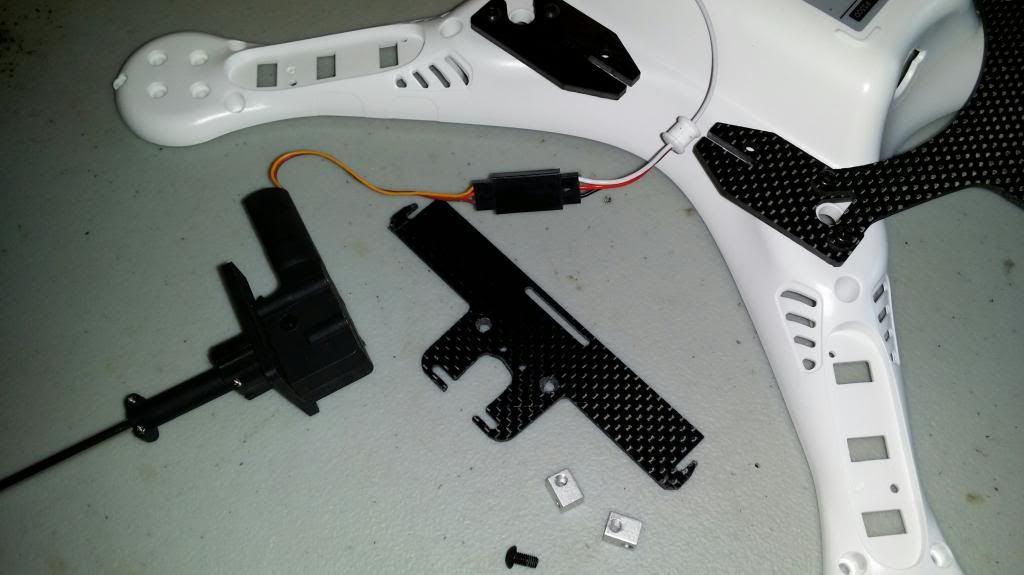
Next I liberated some parts from a set of CF landing gear that was removed due to too much weight- here is where the DIY in you will have to shine through- I would like to have dewey make a special mount, and then put it together but I doubt there would be enough demand- but based on what I have done here, he could make a few measurements and put something together rather easily if he, or someone else with a 3d printer was motivated. It would reduce the weight by half I believe from my mock up.

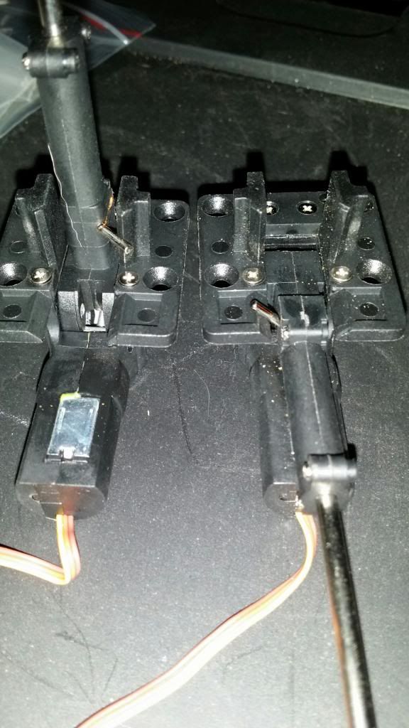
I too the leg ount portions, and then using a dremel to notch out for the gear to lower, I then took the trigger plate off the retract, used it as a template, and drilled the bolt holes- I used 2 of the intended holes on the plate for reinforcement bolts to tiny aluminum blocks with threads (M2x4) I then reused the screws to mount the plate back on as the 2 prongs are the trigger to stop these servoless motors (which shut off power draw after 10 seconds... feckin SWEET!)


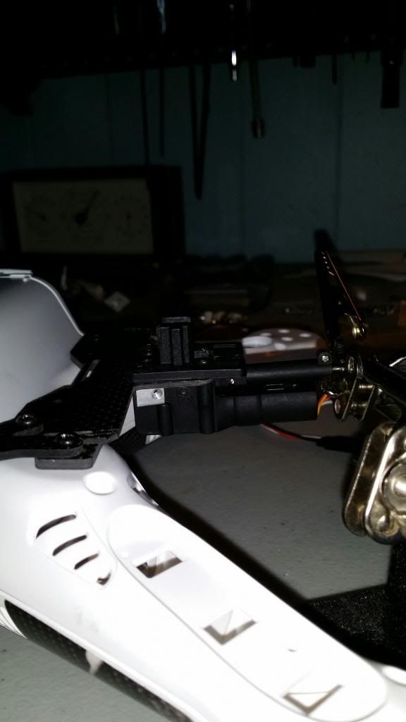
Notice the stock white grommets for the wires? They will route through the shell in the side exactly where the top and bottom meet- I will dremel a half circle notch top and bottom, and this will sandwich between the halves making a tight support on the wire and a clean look.


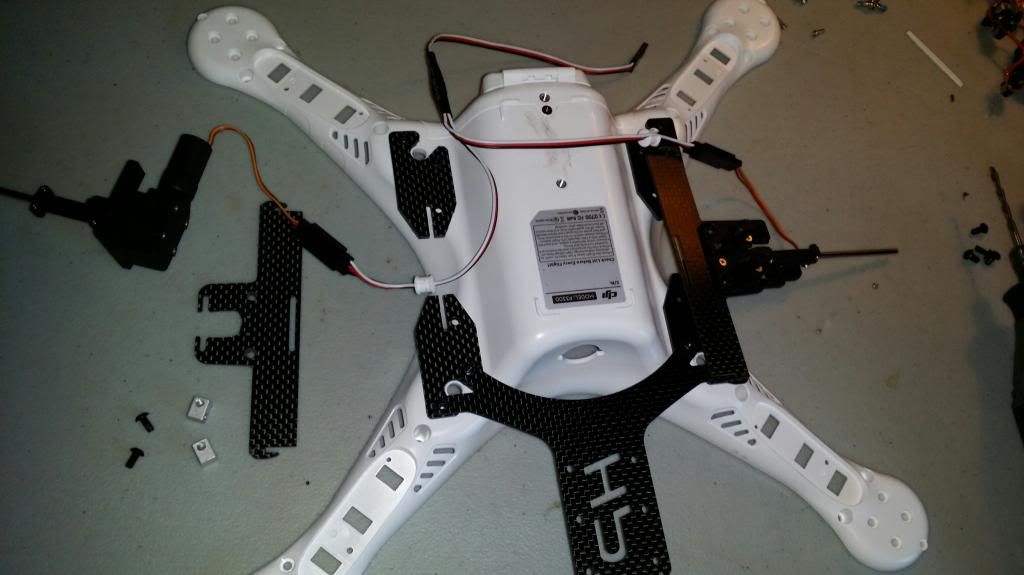
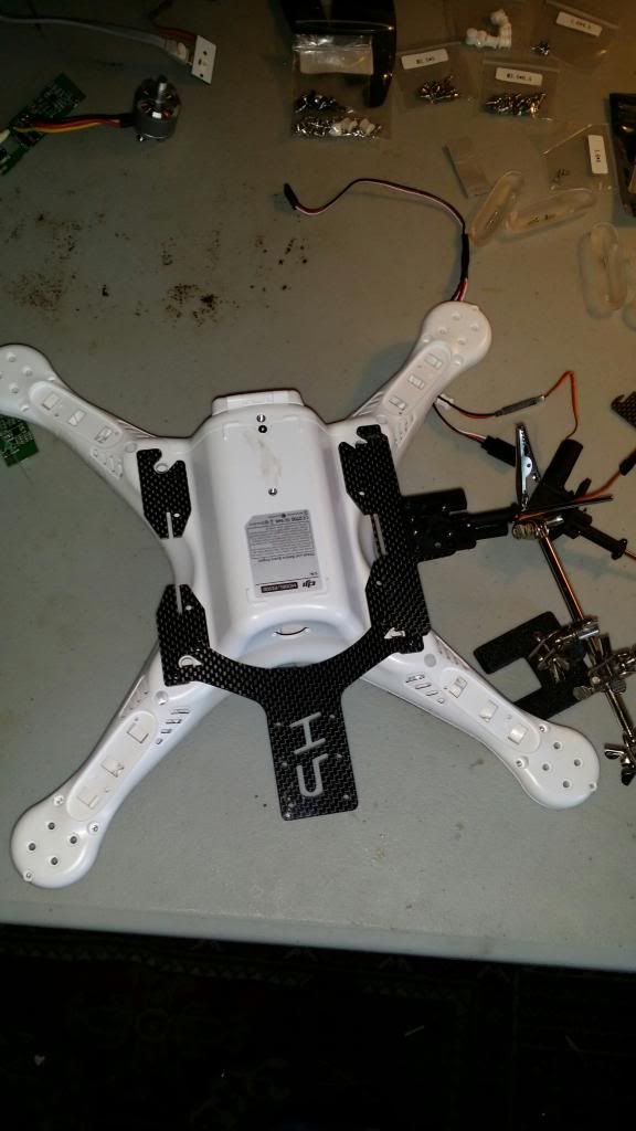
Here is a closeup of right before I decided where to place the bolts, or how to mount the landing gear assembly and plate to the slots which mount at the original landing gear location- I am using the mag glass as a jig to hold it while I contemplate- I think I will gorilla glue it as it does not need to be removed and that may save me a gram.


Once the t-motors get here (new 2.0 versions) and I get the guts all back in, I will see about posting up a killer video to make all you fixed leg Phantom pilots jelly.... neener-neener.
 
jasperthayer said:
You should plan on your "killer" video literally killing your phantom when you try to fly it in GPS mode with the legs retracted and the GPS coordinates become disrupted and your Phantom flies away! Perhaps that's why no one else has retractable legs on a Phantom?

Explain how that will happen please?
 
Ozzyguy said:
I have one thing to say. Totally feckin awesome!

Thank you-

To address the naysayer up there who thinks they know so **** much- the original stock leg will be cut, and the original stock compass mount will be fixed- so no 360 degree shots without something getting in the way on a 3 axis gimbal- but it is in the back so no worries.

I have decided to go ahead and glue the plate to the tabs- no need to add bolts and if the gorilla glue proves to weaken (never seen it do it before) then I will add bolts later.
 
Changed my mind... had the glue in my hand, was about to apply it, and then it dawned on me: I can allow for different weight set ups- and since I do not know how the Phantom will balance with the gimbal and vtx out back, this gives me a slight bit of forward and backward adjustable movement to compensate and not stress the struts either to the front or back; if I can get dead balls on, then I can design lighter weight carbon legs than originally planned saving more weight.

*Oh- and on a side note- I had to order some special M3x10 screws to allow for the stacked material on the compass leg, back rear landing mount... with 2 pieces of CF and the original thick plastic leg, it made for too much distance for the M3x8's that came with the vtx holder.

 
Where are you going to put the compass?
You need to make sure it is not moved, if that is not possible, make sure the orientation stays exactly the same when the legs retract or bad things may happen as the calibration will be off.
 
macheung said:
Where are you going to put the compass?
You need to make sure it is not moved, if that is not possible, make sure the orientation stays exactly the same when the legs retract or bad things may happen as the calibration will be off.

2 posts back I mentioned that.

Let me help by being more specific:

Look at any Phantom that has made the mod to shapeways or similar leg configurations... they are faced with the same or similar problems. I have seen where some folks have simply cut the stock leg off, and left just a "post" you could say dropping down- the same issue exists with the 2 antennae for the receiver- but they will be routed either up the arms, or I am unsure yet- that is actually more of an issue if I am trying to keep as much from the shot as they are running down the 2 front or camera gimbal legs in stock formation. To compensate, I have longer antennae from FrSky that will mount to the receiver- at a couple a bucks each, I have some options and I will experiment and see where, and which lengths work the best (no extreme distances here- max of 1000 meters is all I really care about so this is really not a big issue as dual diversity FASST will definitely do that even with shorty antennae tucked in the shell)

So the stock rear leg and compass and mount will be in the exact spot it was always in.

A 3 axis gimbal is not going to spin in circles on it's pan (or I don't need it too) and with yaw follow, head lock, and some good piloting skills I should never have any issues with legs or props in the footage... and it is cool... so very cool.... did I mention the cool factor? :cool:
 
Hiway, I dig your ingenuity and look forward to your killer video.
 
EMCSQUAR said:
Hiway, I dig your ingenuity and look forward to your killer video.

It's all relative <snicker>

I am currently on hold- I will have to pick this thread back up in a few days as I am waiting on parts. Once the motors get here, I can solder them in and then reassemble this quad and get the bench testing done- then calibrate and I will get her out on the first decent day for some video shots.

(as for "killer" video- that will be subjective)
 
Hiway said:
jasperthayer said:
You should plan on your "killer" video literally killing your phantom when you try to fly it in GPS mode with the legs retracted and the GPS coordinates become disrupted and your Phantom flies away! Perhaps that's why no one else has retractable legs on a Phantom?

Explain how that will happen please?

I'd be interested in an explanation also. Carbon fibre does exhibit electrical/RF properties but from experience has only been a problem at LF/MF/HF frequencies due to close proximity coupling when used as a support for an antenna. Besides there are quite a few all CF frames on the market.

@Hiway: A very nice and ingenious build. I toy'd with the idea of adding retracts to my F550 but instead chose the AeroXcraft CF kit so as to allow mounting of the gimbal further forward of the front arms.

Regards

Nidge
 
Thanks for the kind compliments folks-

My day ended up with a snafu- 2 clients cancelled and the **** wind kicked up so I am grounded for the time.

I went ahead and gathered some pics from yesterday, and took a few more to try and round out some lingering details on this project.

Here is how I routed the gear Y-cable, and the balance plug power lead splitter for the gimbal and vtx power. I do not like the spaghetti wire thing, but I want to be able to connect and disconnect devices and still have a reasonably clean shell... at a bargain. (keep in mind folks- aside from having to buy a new shell, and using old landing gear for material, so far this mod has cost me a grand total of less than $35 USD) The power cables and battery should all fit inside the v1.1.1 in it's proper position when finished.


Here I show the vtx and gimbal power leads exiting the shell with grommet-


As shown in the picture- dremel a tiny channel to slide the wires in- this will make any future disassemble or maintenance far easier. The grommet should be turned so that the slit in it faces down


...so when the board and guts go back on, as you can see, I will hook my power xt60 lead, and the balance lead, and then push them to each side and slide the battery in- I will point out to those who didn't pick up on it- that is a Maddog in there- so it is a tight fit but it works.


...and the board and esc's are down but not bolted:
 
exploded view of gear, plate, cf mount, and hardware made or liberated.
The tip of the white cardboard strip, and the exacto blade point out where the holes for the custom made cf threaded mounts will go to attach the gear plate mount assembly to the landing gear tabs.


A special note on this: when the plate that I pulled from the gear was reassembled to the cf mount- the height caused some rubbing where the gear lowered at the end of travel- the simple solution was to just file down the plate where shown in the picture- I use a rotozip saw blade in the dremel to shave it down- took about 2 seconds.


Here is another side angle of the mounting plate assembly before drilling for final mount to tabs.


****Special note****
When putting the gear and plate and cf mount together- be sure to not trap the pin s shown here- the pin is what triggers the end of travel and shut off for the gear motor.


This is how the pin shuld look- triggered by the plastic tabs on the original plate:
 
jasperthayer said:
... OP made no mention of what they planned to do with the compass on their retractable leg mod, hence my warning.

Understood, and I think I have addressed that suitable to any concerns?
I think because you were so immediately judgmental in your OP it was perceived you were waxing superior, hence the suppositions regarding CF and radio transmissions- especially since compass location is pretty much a given and not something I had considered needing mentioned... no worries.
 
reALIGNed said:
So,................when do you want to make me one? ;)

Bahahahahahaha! Why do you think I posted instructions? If I were really trying to make money of you folks, I would have made the darn things and sold them at $100 a pop- $160 with FrSky Rx and instruction manual. The fact is- for less than $50 in materials, and a $30 receiver with Futaba or similar aftermarket radio, you can do this man. I only have tons of pics and details for anyone who wants to do it.

The only part left is to find tubing (maybe 1/4 fuel line?) that will slide tight over the 3mm shaft, and then find carbon tubes that fit tight to that- a t connector at the bottom and skids mounted and it is done- all but the assembly.

With all of the parts in place, and the tools- this is an afternoon project.

...how much were you willing to pay again? (just curious)
 
Hiway said:
reALIGNed said:
So,................when do you want to make me one? ;)

Bahahahahahaha! Why do you think I posted instructions? If I were really trying to make money of you folks, I would have made the darn things and sold them at $100 a pop- $160 with FrSky Rx and instruction manual. The fact is- for less than $50 in materials, and a $30 receiver with Futaba or similar aftermarket radio, you can do this man. I only have tons of pics and details for anyone who wants to do it.

The only part left is to find tubing (maybe 1/4 fuel line?) that will slide tight over the 3mm shaft, and then find carbon tubes that fit tight to that- a t connector at the bottom and skids mounted and it is done- all but the assembly.

With all of the parts in place, and the tools- this is an afternoon project.

...how much were you willing to pay again? (just curious)

sorry, I was just kidding..........
 

Recent Posts

Members online

Forum statistics

Threads
143,090
Messages
1,467,571
Members
104,974
Latest member
shimuafeni fredrik