Hi everyone,
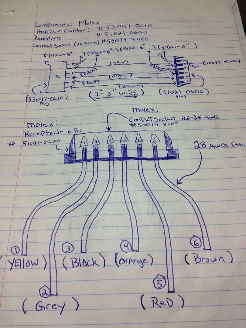
Last week we busted the gimbal and camera so I picked up one of the aftermarket gimbles for a gopro mounting option. I have two mods in mind but can't seem to find a motherboard schematic to verify that they will work.
1) Originally I was going to use my wireless FPV gopro board + my FPV goggles for this but in looking at the motherboard I see two wires on the gimbal ribbon that terminate in blocks labelled 'CAM'. Are these Signal and Ground for video input? If so, can I use my gopro video/ground cable to run my video through the drones native video inputs (and thus get OSD etc)?

2) Is there a known place to tap the switched 12v power the gimbal needs on the top of the motherboard or do I need to pull it entirely and go beneath to hit the primary inputs? Happy to do that but it was just one more thing to do. I imagine somewhere on the gimbal ribbon cable this is present but I've been unable to find it.
All would be resolvable with a proper schematic so I'd love a pointer to that if anyone has access..
Worse case I'll break out the multi-meter and go through them one by one, was hoping for a shortcut.
Tx!
Last week we busted the gimbal and camera so I picked up one of the aftermarket gimbles for a gopro mounting option. I have two mods in mind but can't seem to find a motherboard schematic to verify that they will work.
1) Originally I was going to use my wireless FPV gopro board + my FPV goggles for this but in looking at the motherboard I see two wires on the gimbal ribbon that terminate in blocks labelled 'CAM'. Are these Signal and Ground for video input? If so, can I use my gopro video/ground cable to run my video through the drones native video inputs (and thus get OSD etc)?

2) Is there a known place to tap the switched 12v power the gimbal needs on the top of the motherboard or do I need to pull it entirely and go beneath to hit the primary inputs? Happy to do that but it was just one more thing to do. I imagine somewhere on the gimbal ribbon cable this is present but I've been unable to find it.
All would be resolvable with a proper schematic so I'd love a pointer to that if anyone has access..
Worse case I'll break out the multi-meter and go through them one by one, was hoping for a shortcut.
Tx!


