Hi, I've read many posts on the matter of replacing the 5K linear pot and lever control with a decent rotary pot. I wanted to increase the rotation needed on the control to move the camera through 90 degrees. I did a bit of testing to find the perfect value and settled on 100 degrees of rotation. I then did some test and measure exercises with pots and fixed resistors to achieve my goal.
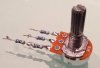
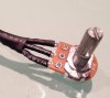
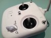
I found I needed a 1k Lin pot and some fixed resistors to get the travel I needed for my control knob. The fixed resistor values are pin 1, 1820 ohms (2x 910 ohm resistors) pin 2, 910 ohms and pin 3, 910 ohms. I fitted the pot on the right hand side of the controller top plate and I can operate it really easily in conjunction with either of the control sticks. My next mod will be to fit a switch and a socket so I can use an external pot controlled by someone else to operate the tilt function on more adventurous tracking and craning shots.
I found I needed a 1k Lin pot and some fixed resistors to get the travel I needed for my control knob. The fixed resistor values are pin 1, 1820 ohms (2x 910 ohm resistors) pin 2, 910 ohms and pin 3, 910 ohms. I fitted the pot on the right hand side of the controller top plate and I can operate it really easily in conjunction with either of the control sticks. My next mod will be to fit a switch and a socket so I can use an external pot controlled by someone else to operate the tilt function on more adventurous tracking and craning shots.
")