- Joined
- Jun 30, 2015
- Messages
- 199
- Reaction score
- 52
- Age
- 49


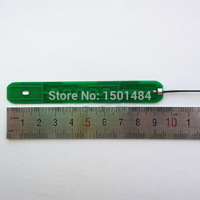
I "guess" it could be a dual band 2.4G/5G antenna, like thisAnyone have a pic of the antenna with the cover removed? It would help us determine the proper location for these boosters.... Then we can put some scotch tape around the plastic cover to act like a stop for optimum placement...
It will make a difference in the beam dispersion pattern. For a tighter beam with more range the Parabolic side (inside curve) needs to point at the P3, this will give you more range but a narrower pattern requiring the antenna to be pointed more towards the P3. With the outside curve pointed at the P3 the beam dispersion will be weaker and much wider. The idea is to narrow and focus the beam towards the P3 increasing range. I built Ham radio antennas for years and we experimented with many different configurations.It shouldn't matter whether to glue/tape the foil inside or outside of the curve. I taped the foil inside the curve because I prefer to tape those 6 legs outside the curve right on the card instead of the foil. I know how fragile of the foil.
Can someone make a phantompilots version?")
Here are a few with the Phantom Pilots logo.
Where are the P3 antennas located on the bird?
Are they vertical or horizontal polarized?
If they are located in the arms, then I would assume they are horizontal, therefore, the RC antennas will need to be aligned the same way. I know the manual displays how the RC antennas should be positioned and that looks like the birds antennas are vertical.
Anyone taken a look?
Indeed. I could see this improving range slightly, however the signal "cone" will be severely reduced. The further you go out, this cone will be so slight that you would almost have to be pointing DIRECTLY at. Very hard to do. The parabolic shape of these DIY antennas are more practical for home wireless routers where distance is much much shorter. This is what they were designed for.It will make a difference in the beam dispersion pattern. For a tighter beam with more range the Parabolic side (inside curve) needs to point at the P3, this will give you more range but a narrower pattern requiring the antenna to be pointed more towards the P3. With the outside curve pointed at the P3 the beam dispersion will be weaker and much wider. The idea is to narrow and focus the beam towards the P3 increasing range. I built Ham radio antennas for years and we experimented with many different configurations.
Very true, and if you look closely at the video you will see the signal strength bouncing around as he tries to keep it pointed at the bird, hard to do with a moving target, much more suitable for a fixed target like a router where you can dial it in.Indeed. I could see this improving range slightly, however the signal "cone" will be severely reduced. The further you go out, this cone will be so slight that you would almost have to be pointing DIRECTLY at. Very hard to do. The parabolic shape of these DIY antennas are more practical for home wireless routers where distance is much much shorter. This is what they were designed for.
Sent from my iPhone using Tapatalk
hey thought to ask you a question since you look more familiar and experienced with radio signals.. someone told me that this setup could cause some problem for a tuned system light-bridge like the one used for P3 transmitter,he mentioned something about: "The core issue is VSWR created by these passive reflectors. tho they create enough reflectance back into the radio to damage the finals of the transmitter" i am concerned for us all to get more understanding if this something to worry about yes or no, or how can you explain his point? thxIt will make a difference in the beam dispersion pattern. For a tighter beam with more range the Parabolic side (inside curve) needs to point at the P3, this will give you more range but a narrower pattern requiring the antenna to be pointed more towards the P3. With the outside curve pointed at the P3 the beam dispersion will be weaker and much wider. The idea is to narrow and focus the beam towards the P3 increasing range. I built Ham radio antennas for years and we experimented with many different configurations.
A high SWR (standing wave ratio) can certainly damage the final stage in older transmitters, and adding this type of modification can increase the SWR. but the newer (DJI) digital PLL transmitter will not be damaged by anything less than about 5:1, which basically is removing the antenna, if the SWR goes too high it will affect performance though. The SWR is the ratio of reflected power to radiated power, as one goes up the other goes down. I do have both a field strength meter and a VSWR meter, the later of which will not be of use as it is inline coaxial. I am going to make a set of these this weekend and will use the FSM to test radiated RF with, and without, which will give a ball park estimate of effectiveness. It will be interesting.hey thought to ask you a question since you look more familiar and experienced with radio signals.. someone told me that this setup could cause some problem for a tuned system light-bridge like the one used for P3 transmitter,he mentioned something about: "The core issue is VSWR created by these passive reflectors. tho they create enough reflectance back into the radio to damage the finals of the transmitter" i am concerned for us all to get more understanding if this something to worry about yes or no, or how can you explain his point? thx
Very interesting information, i think now that you clarified it more i am more concerned to read your results after the test you will make soon, tilll then ill keep using this setup with my custom antennas, i am flying a lot recently long range fpv at least 2.5km each time and this setup helped me alot overall, but I heard my transmitter beeping from time to time randomly like a warning sign but couldn't tell what is its origin as the app didn't show any message or else... I have been hearing it at 2km + randomly coming with custom antennas on, without them i never heard smtgh like that, that's the main reason i am worried to damage my transmitter thinking its a normal beep while it may be some kind of overaload beeping warming sign from the issue you just explained... What do you think? And Thx alotA high SWR (standing wave ratio) can certainly damage the final stage in older transmitters, and adding this type of modification can increase the SWR. but the newer (DJI) digital PLL transmitter will not be damaged by anything less than about 5:1, which basically is removing the antenna, if the SWR goes too high it will affect performance though. The SWR is the ratio of reflected power to radiated power, as one goes up the other goes down. I do have both a field strength meter and a VSWR meter, the later of which will not be of use as it is inline coaxial. I am going to make a set of these this weekend and will use the FSM to test radiated RF with, and without, which will give a ball park estimate of effectiveness. It will be interesting.
Made a couple up this afternoon and took them out for a spin. I flew out to 4000' where I start to drop signal and I still got the same drop at that same location. As long as I was out there I thought I'd spin the drone around. I got better reception with the front end of the drone facing me (from 1-2 bars and a red warning to full 5 bars). I flew out further and made it to 8000'. I started to come back and lost video signal. App asked if I wanted to RTH. I accepted and the map showed it flying to me. Around 5000' I clicked on the screen and video came back. I pressed the X on the screen and accepted control again. I flew back and landed.
So far I did not notice any difference using these. I will do some more testing this weekend and see what I come up with.
The question wasn't if they work, they do, the question was would the mod increase the SWR to the point of harming the final stage transmitter amp. Possible but unlikely with the low power being used. I have pushed 1000 amps into a transmitter final with a 2:5:1 ratio without damage, although it did introduce some harmonics which were not nice.I've used foil wind surver style antennas of my own design on the P2 transmitter anteanns as well as to boost 5 and 8dbi omni antennas. These do work, it's been long proven and scientifically tested. You can check out youtube videos from Tested on this among others.