You are using an out of date browser. It may not display this or other websites correctly.
You should upgrade or use an alternative browser.
You should upgrade or use an alternative browser.
Better Yaw control mod (how to video)
- Thread starter SpikeFinch
- Start date
- Joined
- Jul 17, 2014
- Messages
- 139
- Reaction score
- 0
Sorry, your software is different than mine. I am using 1.1, so the bug might not have been there.

- Joined
- Jul 17, 2014
- Messages
- 139
- Reaction score
- 0
Ok, Looks like the bug might not be on your version.
Getting back to the problem... I have heard that the pots from DJI are not that good and sometimes need to be balanced out if to be used like this. You might have one such pot.
The software can only do a offset for one pot, so if the two pots are not balanced, this is what you will get.
I wish your controller was sitting in front of me....
- Joined
- Jul 17, 2014
- Messages
- 139
- Reaction score
- 0
I appreciate you putting some brain power into it, SpikeFinch.
So this Mouser 20K pot installed may be historically like previous DJI pots and need to be balanced?
I only have one pot installed.
When you say "so if the two pots are not balanced" you are referring if I remove and install the second one I ordered and it has the same asymmetrical response, they both would need to be balanced?
Can you describe balancing? Is this something I can do?
Can anyone else with the 20K mod chime in on their symmetrical or asymmetrical YAW response?
thanks
- Joined
- Jul 17, 2014
- Messages
- 139
- Reaction score
- 0
What I am saying is the "Yaw" controller (pot) that comes from the DJI factory are sometimes not balanced. Thus the offset in software.
You can fix this with resistors , but you need to measure the difference between the legs.
You can fix this with resistors , but you need to measure the difference between the legs.
- Joined
- Jul 17, 2014
- Messages
- 139
- Reaction score
- 0
Member "cougar" had done the balancing mod to a few controllers. I have not run into the problem yet.
He told me "To correct this you need to measure the resistance differences over the two elements and install a resistor on one of the wires to compensate so they are the same (with the pot turned all the way down)."
But I think your on the right track.
He told me "To correct this you need to measure the resistance differences over the two elements and install a resistor on one of the wires to compensate so they are the same (with the pot turned all the way down)."
But I think your on the right track.
Looks to me like you have the wiring between the switch and the potentiometer incorrect based on the original schematic. The yellow wire from the switch should go to the left contact on the pot and not the right contact that is jumpered to the center terminal. Same for the black wire. Can someone double check me on this? Could this be the cause of the problem?
pb7424 said:Looks to me like you have the wiring between the switch and the potentiometer incorrect based on the original schematic. The yellow wire from the switch should go to the left contact on the pot and not the right contact that is jumpered to the center terminal. Same for the black wire.
This had been my primary question from the beginning of the project. Why was it a question?
Because of the Lars' schematic that RemE included with his original drawings.
They are different at the very point you speak, pb7424.
SpikeFinch seems to have produced his Phantom TX yaw mod video based on Lars' version.
I completed my mod in the SpikeFinch-Lars fashion.
Has anyone else followed SpikeFinch's video and not had asymmetrical YAW control?
Has anyone followed RemE's original schematic?
rock&roll,
Eric
Attachments
- Joined
- Jul 17, 2014
- Messages
- 139
- Reaction score
- 0
The difference between the way the two are wired is going to be the direction you need to turn the pot to get min yaw.
In my (Lars schematic)video, CCW will give you Min yaw, In the RemE one it will be CW for min yaw.
In my (Lars schematic)video, CCW will give you Min yaw, In the RemE one it will be CW for min yaw.
That's what I figured and plowed ahead with the project. thanks.
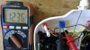
In your opinion, are my pictures clear enough to determine if they are correctly wired as pb7424 questioned?
I'm currently fiddling with inline resistors.
best to you
In your opinion, are my pictures clear enough to determine if they are correctly wired as pb7424 questioned?
I'm currently fiddling with inline resistors.
best to you
- Joined
- Jul 17, 2014
- Messages
- 139
- Reaction score
- 0
It sounds like everything is working, correct? Just yaws one direction more than the other? I would be balancing the pot (loop), yes.
I'm placing various resistors 1 at a time across the black wire from the yaw gimbal pot or after the 20K pot. no luck.
The Rudder values at maximum left or right are all jacked up.
Examples:
original R-values before resistors with maximum 20K resistance: -201(left)/86(right)
100 ohm resistor across the 20K pot outgoing wire - R-values: -195/80
1.2K ohm resistor across the 20K pot outgoing wire - R-values: -72/204 (why does the right R-value increase?)
1.2K ohm resistor across yaw gimbal to 20K pot wire - R-values: -75/200
I suppose I should talk with cougar about how to internally test the yaw gimbal pot resistance.
Testing the Mouser pot is easy because you can see the input/output pins.
I do not know where the contacts are for the yaw gimbal pot.
disassembly of stick required?
- Joined
- Jul 17, 2014
- Messages
- 139
- Reaction score
- 0
Talking to cougar is a good plan.
Are you placing the resistor in line or across the pot? It must be in in-line, not across the pot.
Also, must be after the switch or all connections.
Are you placing the resistor in line or across the pot? It must be in in-line, not across the pot.
Also, must be after the switch or all connections.
Just did this mod using the Mouser 20k pot. 20k is too high. 1/4 turn seems optimal. Anything beyond 1/2 turn and it wouldn't be responsive enough to fly. Full turn and it doesn't hardly move. Might take 2 minutes to do full 360* turn. I think 10k is ideal. Going to order one and replace the 20k to get more resolution.
-Scott
-Scott
Similar threads
- Replies
- 0
- Views
- 1K
- Replies
- 1
- Views
- 1K
- Replies
- 0
- Views
- 2K
- Replies
- 0
- Views
- 705